Jul 2025 - Present
MIT Motorsports
Driverless software and algorithms.
Overview
I am working on the driverless software stack for MIT Motorsports’ autonomous racecar. The core challenge is to drive through a Formula SAE autocross-style track defined by blue and yellow cones, keeping the car between the left and right boundaries while planning a fast, stable path forward.
The full vehicle stack is built around an NVIDIA Jetson AGX Orin 64 GB, an Ouster OS1 128-channel LiDAR, three Blackfly cameras, and a VectorNav VN-300 IMU. For day-to-day development and testing, we run the same autonomy stack on a smaller rover testbed before moving onto the racecar. Our long-term goal is to compete in the Driverless Cup at FSAE Michigan 2027.
The autonomy problem is divided into four main subsystems: perception, state estimation, planning, and control.
The Stack
Perception
Perception currently uses a LiDAR-only cone detection pipeline. Raw Ouster point clouds are filtered to a region of interest, ground points are removed, and the remaining points are clustered in the XY plane using Euclidean/DBSCAN-style clustering. Each cluster is reduced to a cone centroid.
For cone colors, the LiDAR-only classifier builds blue and yellow cone chains using nearest-neighbor ghost-cone seeding, then scores candidate chains with heading and turn-consistency checks. Camera detections and YOLO can be added later to validate or replace LiDAR-only color assignments, but the current direction keeps the pipeline usable even before vision is fully integrated.
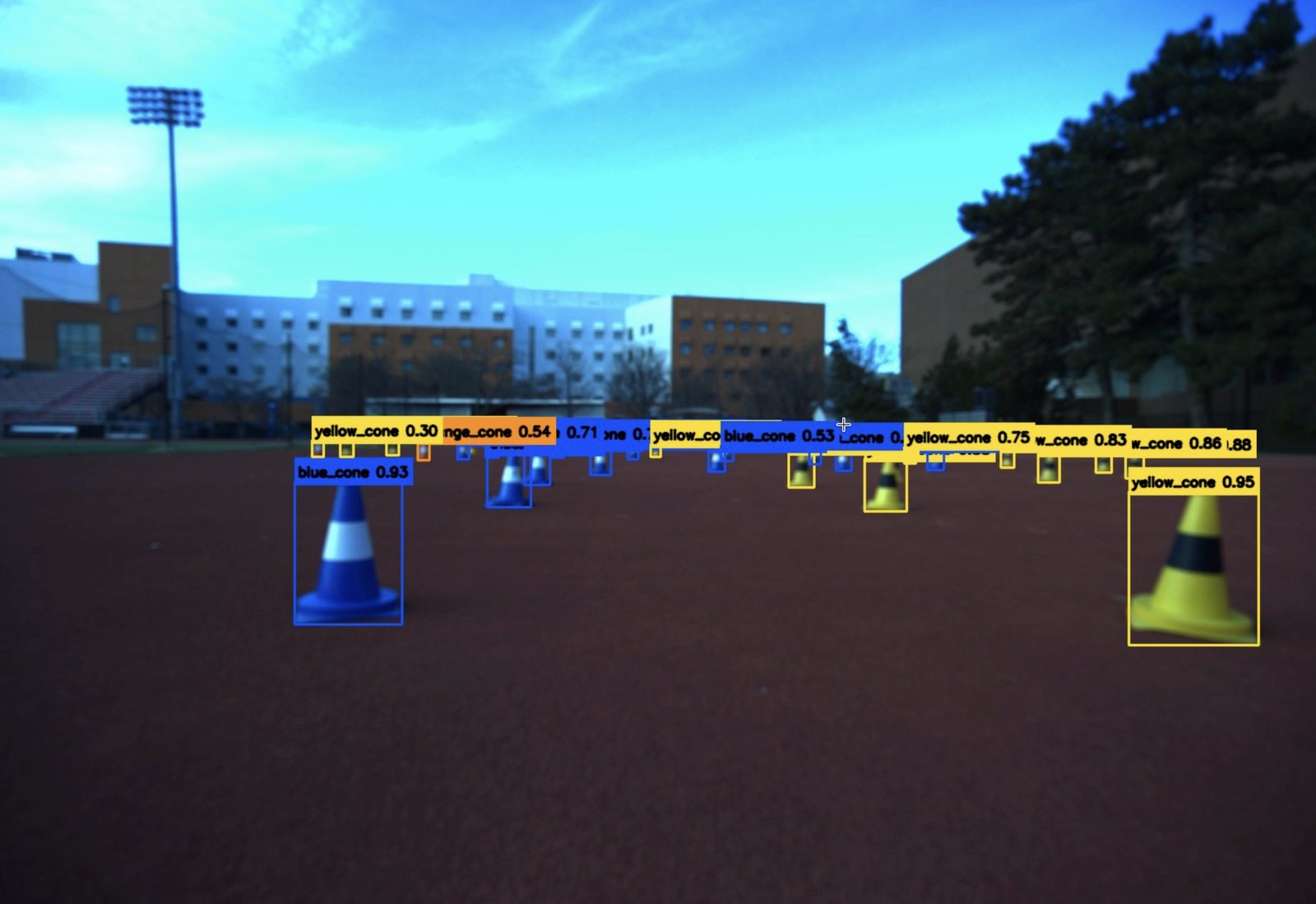
State Estimation
State estimation uses the robot_localization EKF package to fuse GPS, ground-speed odometry, and IMU data into a filtered vehicle state. GPS is converted through navsat_transform_node into /odometry/gps, the ground-speed sensor provides forward velocity, and the VectorNav IMU contributes yaw-rate and angular motion.
The fused estimate publishes a filtered pose and velocity stream, such as /odometry/filtered, along with the TF frames needed by planning and control.
Planning
Planning consumes the perceived colored cone centroids, transforms them into the planning frame, and filters to nearby cones that matter for the current horizon. If only one side of the track is visible, the planner can create virtual cones to maintain a usable corridor.
From there, it uses Delaunay triangulation to connect cones, takes midpoints between opposite-color cone edges, builds a graph of candidate centerline points, and runs Dijkstra/search to choose the forward path. The selected centerline is smoothed with a spline and published as a /path.
Control
Control follows the planned path using the current state estimate and odometry. The stack supports path-tracking approaches such as Pure Pursuit and Stanley: Pure Pursuit selects a lookahead point and computes steering curvature, while Stanley uses cross-track and heading error from EKF odometry.
The controller publishes desired velocity and steering commands, which pass through a command-mux safety gate before reaching the ODrive motor and steering hardware.
Next Steps
The next goals are to reduce loop times, run safely at higher speeds, add SLAM, implement a minimum-curvature racing line, add velocity profiling, and move toward MPC for control.